3 Joint Robotic Arm With Claw
Hi, my name is Sasha! The project that I chose to build was the 3 joint robotic arm with claw and potentiometers. This robotic arm will function through the use of micro servo and potentiometers. This robotic claw will be able to hold different small objects.

| Engineer | School | Area of Interest | Grade |
|---|---|---|---|
| Sasha | Marin Academy | Biomedical Engineering | Incoming Senior |
My project
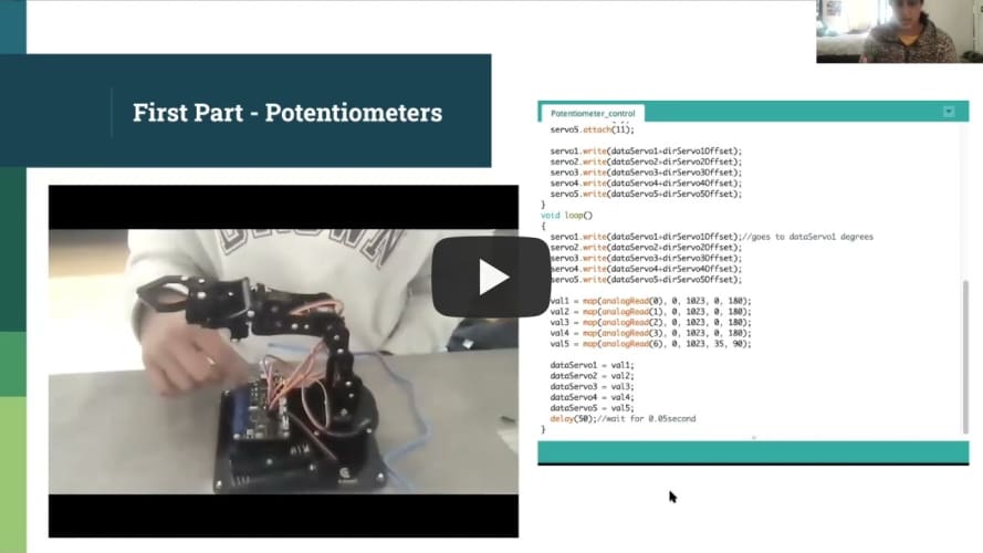
Below is the link to my presentation summarizing the whole project.
3 Joint Robotic Arm Presentation
Below is a picture of my completed robotic arm. This picture shows the actual robotic arm as well as the circuit board that have the potentiometers which control the robotic arm.

Final Milestone
My final milestone showcases my whole project. In this video I demonstrate both the regular robotic arm functioning as well as the robotic arm with modifications that I added. The modification that I added to the robotic arm was using GUI or graphic user interface to control the arm. This means that I can control my robotic arm using a program on my computer instead of the potentiometers. To do this I used python and arduino to control the robotic arm via GUI. During this one challenge thatI faced was the python interface not working properly. To solve this problem I went through and checked all my connections and restarted the program a couple times and I was able to get it working again. Throughout this project I experienced different challenges but I was able to work through them and I gained great probelm solving skills from the challenges.
Second Milestone
My second milestone was building the actual robotic arm. For this I used all the pieces in the kit and put together the robotic arm. This arm is controlled by potentiometers and servos so I had to make sure all the connections were properly working. Another key component in building this arm was the arduino code being sent to the arm. In this code it established the servos and the rotation of each servo. The code also outlined the connections between the potentiometer and servo so the potentiometer could correctly control the servos. For this milestone one of the challenges that I faced was the servo was not properly functioning and rotating. This was a big challenge but after carefully checking my connections and making sure all the actual pieces were properly connected I was able to get the arm to properly work.

First Milestone
My first milestone was connecting a micro servo and potentiometer controlled via arduino. The micro servo and potentiometer were connected through a breadboard and the arduino. I used code written out in Arduino on my laptop to control the potentiometer and servo. The code essentially translated the potentiometer movements to the servo movemens so that these two seperate pieces were synched together. To do this there were several connections that I had to make either directly from potentiometer to servo or servo to arduino to potentiometer. Although I was successful in making these connnections at first the servo was not working properly. After carefully reviewing all my connections and making sure there were no small errors the servo was properly functioning.

Bill of Materials
This is a table containing all the items needed for milestone one and the robotic arm. It contains the item, quanitity, price and where to buy the item.
| Item | Qty | Price | Where to Buy |
|---|---|---|---|
| Adeept Robotic Arm Kit | 1 | $64.99 | https://www.amazon.com/dp/B087R8DLG6 |
| Breadboard | 1 | $6.75 | https://www.amazon.com/BB400-Solderless-Plug-BreadBoard-tie-points/dp/B0040Z1ERO |
| Potentiometer | 1 | $1.85 | https://www.tubesandmore.com/products/potentiometer-alpha-linear-38-bushing |
| Micro Servo | 1 | $5.95 | https://www.adafruit.com/product/169 |
| Jumper Wires | 6 | 10¢/wire | https://www.amazon.com/Breadboard-Jumper-Wire-75pcs-pack/dp/B0040DEI9M |
| Arduino Uno Board | 1 | $27.60 | https://store-usa.arduino.cc/products/arduino-uno-rev3?selectedStore=us |
| Arduino IDE | 1 | $0 | https://www.arduino.cc/en/software/ |
Schematics
This is a schematic of the adeept circuit board used for my robotic arm. This board connects to my computer which contains the code for the arm. This board also has the potentiometers that control the robotic arm.

How to Recreate the Project
For this project one really important thing to keep in mind before assembling the robotic arm is testing all the micro servos. Sometimes the micro servos don’t work or there motors die and it can be really challenging to replace them when the robotic arm is already assembled. In order to check the servo you can use the a simple set up with potentiometers, arduino and micro servo like I built in my first milestone to make sure all the micro servos work. This simple extra task can lead to a smoother building process and a more successful robotic arm.
Robotic Arm Code
Below is my code I used to control the original robotic arm. This code is through arduino and it controls both the micro servos in the arm and the potentiometers controlling the micro servos.
#include <Servo.h>
Servo servo1;//create servo object to control a servo
Servo servo2;
Servo servo3;
Servo servo4;
Servo servo5;

int dataServo1 = 90;
int dataServo2 = 90;
int dataServo3 = 90;
int dataServo4 = 90;
int dataServo5 = 90;

float dirServo1Offset = 0;
float dirServo2Offset = 0;
float dirServo3Offset = 0;
float dirServo4Offset = 0;
float dirServo5Offset = 0;
int val1;
int val2;
int val3;
int val4;
int val5;
void setup()
{
  servo1.attach(9);
  servo2.attach(6);
  servo3.attach(5);
  servo4.attach(3);
  servo5.attach(11);

  servo1.write(dataServo1+dirServo1Offset);
  servo2.write(dataServo2+dirServo2Offset);
  servo3.write(dataServo3+dirServo3Offset);
  servo4.write(dataServo4+dirServo4Offset);
  servo5.write(dataServo5+dirServo5Offset);
}
void loop()
{
  servo1.write(dataServo1+dirServo1Offset);//goes to dataServo1 degrees
  servo2.write(dataServo2+dirServo2Offset);
  servo3.write(dataServo3+dirServo3Offset);
  servo4.write(dataServo4+dirServo4Offset);
  servo5.write(dataServo5+dirServo5Offset);

  val1 = map(analogRead(0), 0, 1023, 0, 180);
  val2 = map(analogRead(1), 0, 1023, 0, 180);
  val3 = map(analogRead(2), 0, 1023, 0, 180);
  val4 = map(analogRead(3), 0, 1023, 0, 180);
  val5 = map(analogRead(6), 0, 1023, 35, 90);

  dataServo1 = val1;
  dataServo2 = val2;
  dataServo3 = val3;
  dataServo4 = val4;
  dataServo5 = val5;
  delay(50);//wait for 0.05second
}
Below is a sample of the code that is used to support the graphic user interface which is the modification I made to the robotic arm. For this modification I used a python based program to control the robotic arm instead of the potentiometers.
/*
 * KEY4x4 and MPU6050 cannot be 1 at the same time. Otherwise, insufficient capacity will be indicated.
 * When BUZZER is 1, the infrared sensor cannot be used, but the BUZZER can be used
 * When BUZZER is 0, the infrared sensor can be used, but the BUZZER cannot be used
 *(you can change these values as you apply them)
*/
#define KEY4x4  0
#define MPU6050 0
#define BUZZER   0


#include <ArduinoJson.h>
#if !BUZZER
#include <IRremote.h>
#endif

#include <Servo.h>

#include <Wire.h>
#include <LiquidCrystal_I2C.h>
#include <dht11.h>
#include <Keypad.h>
LiquidCrystal_I2C lcd(0x27,16,2);


dht11 DHT11;

#if !BUZZER
char RECV_PIN = 11;//The definition of the infrared receiver pin 11
IRrecv irrecv(RECV_PIN);
decode_results results;
#endif
Servo myservo[5];
char a = 2;
char b = 3;
char c = 4;
char d = 5;
char e = 6;
char f = 7;
char g = 8;
char p = 9;
char dp = 9;
char d4 = 10;
char d3 = 11;
char d2 = 12;
char d1 = 13;
char APin ;
char BPin ;
int Pin0 = 0;
int Pin1 = 0;
int Pin2 = 0;
int Pin3 = 0;


char line[60] = ""; // Serial data
int ret = 0;
char pingPin,trigPin;


#if MPU6050

unsigned long now, lastTime = 0;
float dt;                                   //derivative time
unsigned short times = 200;             //Sampling frequency
int16_t ax, ay, az, gx, gy, gz;             //Accelerometer gyroscope raw data
float aax=0, aay=0,aaz=0, agx=0, agy=0, agz=0;    //Angle variable
long axo = 0, ayo = 0, azo = 0;             //Accelerometer offset
long gxo = 0, gyo = 0, gzo = 0;             //Gyroscope offset

float pi = 3.1415926;
float AcceRatio = 16384.0;                  //Accelerometer scaling factor
float GyroRatio = 131.0;                    //Gyroscope scale factor

uint8_t n_sample = 8;                       //The number of samples sampled by accelerometer filtering algorithm
float aaxs[8] = {0}, aays[8] = {0}, aazs[8] = {0};         //Sample the queue on the x and y axes
long aax_sum, aay_sum,aaz_sum;                      //X,y axis sampling queue x,y axis sampling and

float a_x[10]={0}, a_y[10]={0},a_z[10]={0} ,g_x[10]={0} ,g_y[10]={0},g_z[10]={0}; //Accelerometer covariance calculation queue
float Px=1, Rx, Kx, Sx, Vx, Qx;             //The kalman variable on the X-axis
float Py=1, Ry, Ky, Sy, Vy, Qy;             //The kalman variable on the Y-axis
float Pz=1, Rz, Kz, Sz, Vz, Qz;             //The kalman variable on the Z-axis

const int MPU_addr=0x68; // I2C address of the MPU-6050
int16_t AcX,AcY,AcZ,Tmp,GyX,GyY,GyZ;
#endif

#if KEY4x4
const byte ROWS = 4; //four rows
const byte COLS = 4; //four columns
//define the cymbols on the buttons of the keypads
char hexaKeys[ROWS][COLS] = {
  {'1','2','3','A'},
  {'4','5','6','B'},
  {'7','8','9','C'},
  {'*','0','#','D'}
};
byte rowPins[ROWS] = {9, 8, 7, 6}; //connect to the row pinouts of the keypad
byte colPins[COLS] = {5, 4, 3, 2}; //connect to the column pinouts of the keypad

//initialize an instance of class NewKeypad
Keypad customKeypad = Keypad( makeKeymap(hexaKeys), rowPins, colPins, ROWS, COLS);
#endif

 int ST = 0; //Pin connected to ST_CP of 74HC595
 int SH = 0;//Pin connected to SH_CP of 74HC595
 int DS = 0; //Pin connected to DS of 74HC595

void setup() {
  memset(line, 0, sizeof(line));
Serial.begin(115200); // Open the serial port and set the data transmission rate of 115200

}

void loop() {
  DynamicJsonDocument  jsonBuffer(100);
// Operate when the serial port is available
if (Serial.available() > 0) {

//  read incoming data: read up to \n, or up to 500 characters
ret = Serial.readBytesUntil('\n', line, 100);
//Serial.println(line);
  deserializeJson(jsonBuffer, line);
JsonObject root = jsonBuffer.as<JsonObject>();

  my_cmp(root);

memset(line, 0, sizeof(line));
}